E-motor Cooling With PreonLab 5.2

July 27, 2022
Siddharth Marathe and Loïc Wendling
The latest PreonLab release for version 5.2 introduced some exciting new features such as Continuous Particle Size (CPS), sensor planes for the solid solver, and heat field.
In this article, we will look at the benefits of these features for thermodynamic applications with the example of electric motor cooling.
There is indeed a large range of applications across different industries which make use of electric motors for power generation.
The focus of this article will be on electric motors in the context of electric vehicles.
Share:

Introduction

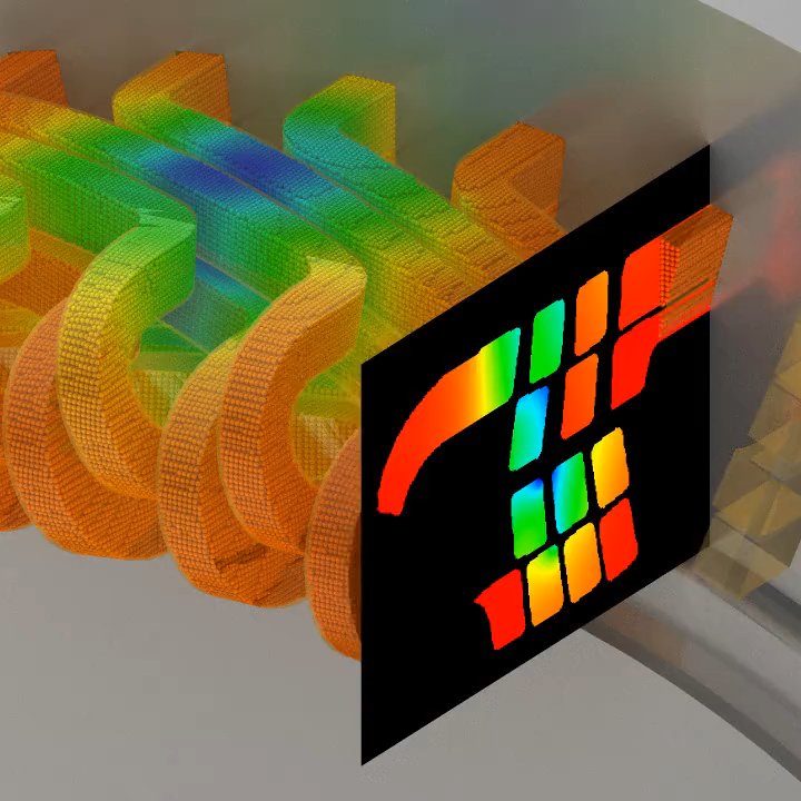
Electric motor or e-motor cooling is a vital aspect of the thermal management system for vehicles. Efficient cooling leads to significant boosts in performance and contributes towards the use of smaller motors for a given application or increasing the range of batteries. As a result, it is crucial to meet the space, weight, and cost targets of the project.
Making use of CFD simulations can deliver great insights into the e-motor cooling process to optimize the design stage. However, running comprehensive simulations for e-motor cooling can be rather costly in terms of computational power.

This is a great opportunity to apply the new Continuous Particle Size (CPS) feature which allows fine particles for regions where we have a large amount of heat transfer, and efficiently increases the particle size of the fluid in the regions of lower interest. Details about Continuous Particle Size (CPS) can be found in the article: “Continuous Particle Size (CPS) and Adaptive Refinement“. As a result, the number of particles required in the simulation is minimized and the computational effort can be reduced.  

Apart from this, a volumetric heat source is necessary to best simulate the heat generated within the components of the e-motor. Up until now only surface thermal boundary conditions were available in PreonLab.
Now with version 5.2 and PreonLab’s new feature called heat field, a user-defined heat source can be generated within a volume. The heat source can be applied to the domain and controlled spatially via an embedded geometry or even a point cloud resource.
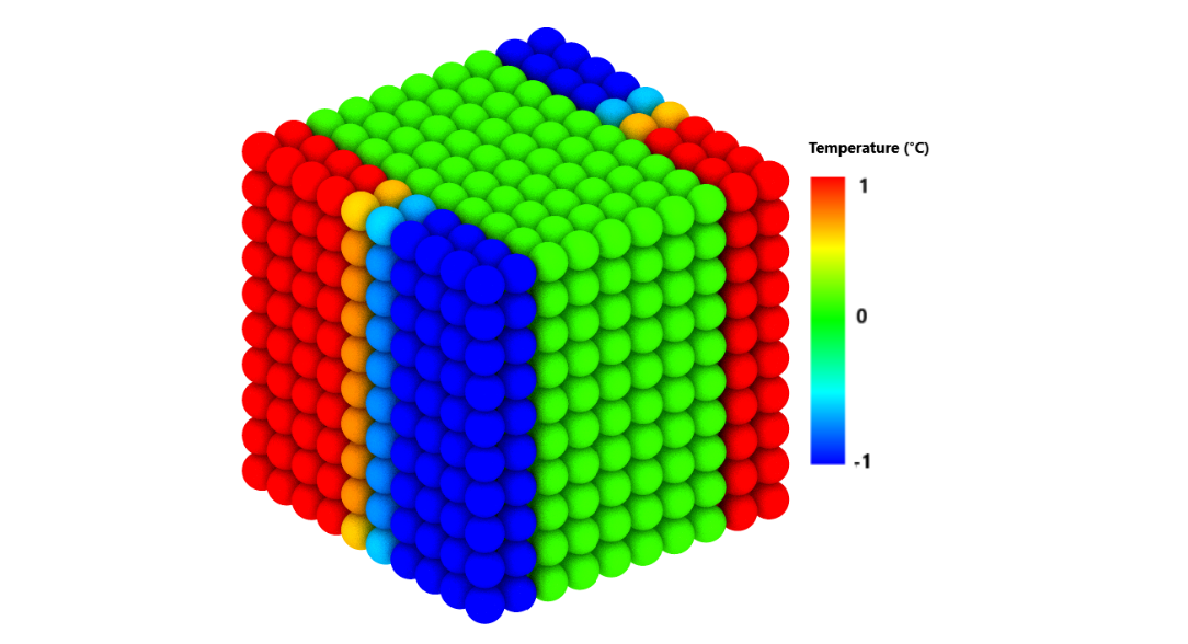
A point cloud resource object in PreonLab is a cloud of sampling points that can be assigned with different user-defined values such as heat source strengths.
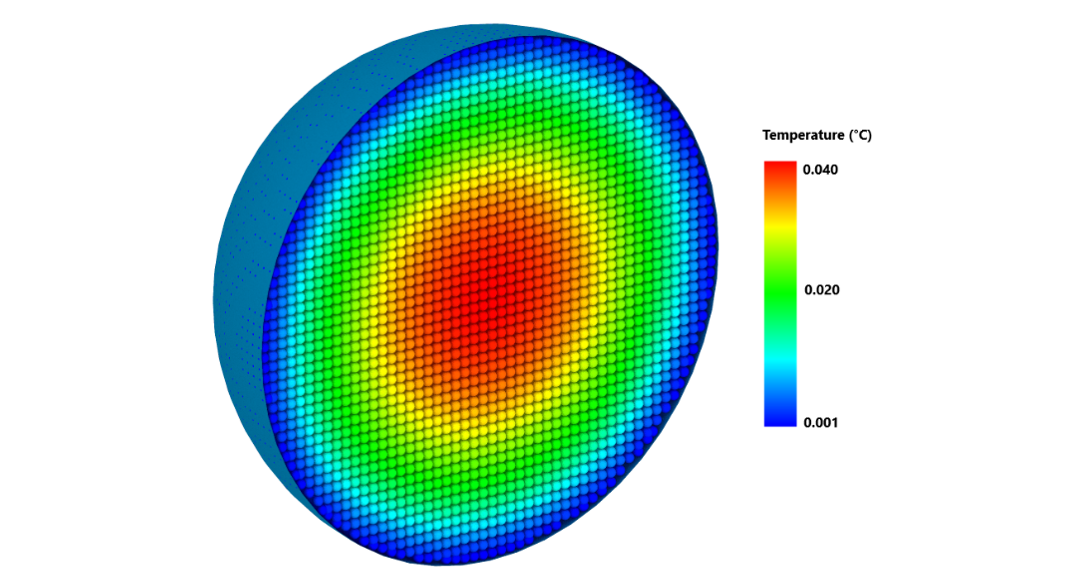
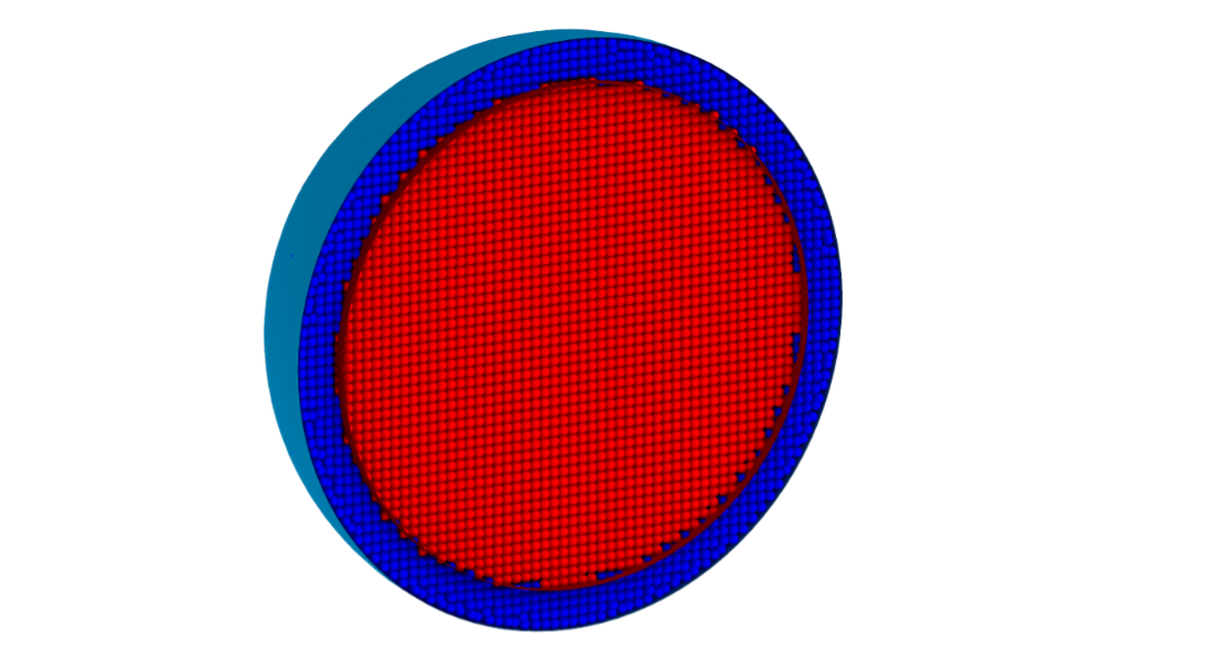
Figure 1a depicts the temperature distribution in a sphere resulting from a uniform heat field, Figure 1b showcases the use of an embedded spherical geometry to control where the heat field is applied (red particles), and Figure 1c shows the concept of applying the heat field via a point cloud resource object.

Figure 1a: Temperature distribution resulting from a uniform heat field.
Figure 1b: Heat field constrained by an embedded spherical geometry.
Figure 1c: Heat field as a point cloud resource (blue particles are assigned negative heat source values and the red particles are assigned positive heat source values).
E-Motor – need for cooling

Why is cooling necessary for
e-motors?

An e-motor converts electrical energy into mechanical energy. Force is usually generated in the form of torque on the shaft of the motor via the interaction between a magnetic field and an electric current in a wire winding.
During this process, a large quantity of heat is generated within the windings, due to the Joule heating effect, which can damage the components inside the e-motor and affect the efficiency of the e-motor.
This heat needs to be removed from the system using appropriate cooling methods to protect the components of the e-motor.
Simulation results

Analysis for three types of cooling

For the examples in this article, we consider an e-motor with hairpin-style copper windings as is shown in Figure 2. The temperature within the windings can reach up to 120°C.

Figure 2: Main components of an e-motor.

Three types of cooling are investigated in this article: Jet cooling from the rotating shaft, jet cooling from injection points along the stator, and jacket cooling.
The e-motor is cooled with oil as a coolant for the jet cooling method and water or a mixture of water and ethylene glycol as the coolant for the jacket cooling method. This is done because we do not want the water to come into contact with the components of the e-motor directly.
Furthermore, the oil is already available in the gearbox and can be used for cooling the e-motor without much additional effort.

Note: For demonstration purposes, only a wedge-shaped section of the e-motor was simulated for all three types of cooling investigated in this article.

Cooling method 1

Jet cooling from inlets within the rotating shaft

Figure 3 shows the inlets, through which the oil is emitted onto the windings from within the rotating shaft. The oil flows through the center of the shaft and is emitted outwards as the shaft rotates.

Figure 3: Inlets for oil cooling within the rotating shaft.

The cooling of the windings by the oil which flows from the inlets within the rotating shaft is shown in the following video. The total simulation time was 26 hours on 64 CPUs.

Please agree to the transfer of data to third parties as set out in our privacy policy.

Jet cooling simulation showing the cooling of the copper windings by oil emitted from inlets within the rotating shaft.

During simulation setup, CPS is applied, so that a coarse particle size can be used for the particles which are emitted from the shaft outlets, while fine particles can be used near the windings to accurately capture the large heat transfer between the coolant and the windings.
As the oil diffuses away from the shaft and spreads on the winding, it absorbs heat from the hot surface. The corresponding color change of the oil can be observed quite well in the video above.
Cooling method 2

Jet cooling from inlets in the stator

Similarly, the copper windings can also be cooled by oil which is emitted out of injection points along the stator. In the following section, we look at the simulation results for this type of cooling.
Using CPS, a larger range of particle sizes can be used for the simulation. As can be seen from Figure 4, it is possible to use particles with a size as low as 0.125 mm at the impingement area and a particle size of 0.25 mm near the windings.
Once the oil flows away from the windings, the particle size is increased to 1 mm. Consequently, the simulation time can be reduced from 26 hours (achieved using 2 levels of refinement with PreonLab version 5.1) to 23 hours on 64 CPUs.

Figure 4: Different particle sizes used for oil during simulation with CPS.

Conjugate heat transfer:
An important aspect is the analysis of the conjugate heat transfer between the oil and the windings. For this purpose, a solid solver is added to simulate the heat transfer within the copper windings. The conjugate heat transfer can be observed in the following video:

Please agree to the transfer of data to third parties as set out in our privacy policy.

Jet cooling simulation showing the cooling of the copper windings by oil emitted from inlets along the stator.

In the video above, the copper windings are color-coded according to temperature. We can see that the copper windings have an initial temperature of 110°C, due to the heat generated by the heat field.
The temperature rises further to around 116°C wherever the oil does not interact with the windings and red hotspots are created.
The temperature of the copper windings reduces at locations where the oil stream interacts with the heated-up copper windings and the oil gets hotter as it absorbs this heat. The oil in the video is color-coded with temperature as well.
This conjugate heat transfer simulation required only 4 hours on 64 CPUs for the wedge-shaped section of the e-motor.
Results within copper windings:
Along with investigating the conjugate heat transfer between the oil and the windings at the surface, it can also be interesting to gain information about the heat distribution within the copper windings.
For this purpose, PreonLab 5.2 has made it possible to use sensor planes in combination with the solid solver to measure values at any location within solids – in this case, the copper windings.
It is thus possible to visualize hot spots within the windings, as it can be seen from the following video, and understand the effectiveness of the chosen cooling method.

Please agree to the transfer of data to third parties as set out in our privacy policy.

Application of a sensor plane to analyze the heat distribution within the copper windings.

Cooling method 3

Jacket cooling

In addition to the two types of jet cooling discussed so far in this article, the e-motor could also be cooled by jacket cooling, where the coolant flows through channels without coming into direct contact with the internal components of the e-motor, as is shown in Figure 5.
The heat field comes in handy during this investigation as well to generate heat not only within the windings but also within the stator. This is necessary to model the iron losses which occur within the ferromagnetic core.

Figure 5: Jacket cooling: The channel through which the water flows is colored blue in the image.

It is possible to analyze how the coolant, which flows through the channel, removes heat away from the windings and the stator during simulation. In Figure 6, it can be observed that the cooling effect reduces in the direction of the flow as a result of the coolant heating up.
A cross-sectional view of the jacket cooling setup is also shown in Figure 6.
Figure 6: Cross-sectional view of the jacket cooling setup (left) and heat distribution in the winding and stator due to the flow of water through the channel (right).

Based on all the information gathered via analysis of the three types of cooling, the design engineer can vary the cooling system parameters such as the type of coolant and the cooling pattern which includes the size, location and number of oil inlets and perform further simulations.

Oil infiltration in the air gap

Apart from the effectiveness of cooling, information about the oil infiltration in the air gap between the rotating shaft and the stator can be vital for design engineers.
When it comes to optimizing the design of the e-motor, this oil infiltration needs to be minimized.
The air gap is considerably smaller than the other components of the e-motor and we need very fine particles at this location to resolve the flow properly during simulation. This can be observed in Figure 7.
Due to the large size ratio of the particles possible with the CPS feature, the infiltration of oil in the air gap can be analyzed as part of the same simulation along with the jet cooling simulation.
Without CPS, this would be rather difficult in terms of computational effort.

Figure 7: Oil infiltration in the air gap between the rotating shaft and the stator.

Conclusion

The e-motor cooling case explored in this article is a great starting point for future validation studies.
It showcases the usefulness of the new features introduced in PreonLab 5.2 towards reducing computation costs and performing in-depth analysis for complex cases including (but not limited to) thermodynamic phenomena.
RELATED ARTICLES

LEARN MORE ABOUT PreonLab Updates

How to get started with
Preonlab CFD software?
Get in Touch