Electric motors (e-motors) are crucial in modern technology, powering various applications from household appliances to electric vehicles. A key challenge in e-motor design is managing the heat generated during operation. This heat primarily arises from the Joule effect, where electrical resistance in the motor’s windings converts electrical energy into heat. The extent of this heating is proportional to the square of the current and the resistance, making it a critical factor in determining motor efficiency. Excessive heat can lead to the degradation of motor components, reducing efficiency and potentially shortening the motor’s lifespan. As a result, implementing effective cooling strategies is essential for maintaining optimal performance and ensuring long-term reliability, which ultimately enhances the range of the e-vehicle.
Video 1: Cooling Simulation of a 360° Section of an E-motor with PreonLab 6.1.
CFD analysis of e-motor cooling efficiency is a complex task requiring expertise and advanced simulation tools. PreonLab offers unique capabilities that simplify and accelerate virtual e-motor development. Utilizing the Smoothed-Particle Hydrodynamics (SPH) method, PreonLab eliminates the need for cumbersome surface preparation and meshing, saving valuable time and human resources. PreonLab’s quick setup and accelerated computation shorten the turnaround time of research and development by allowing the designers to quickly iterate through design proposals and evaluate different design strategies in parallel.
Video 2: Multiple Oil Jets Cooling an Electrical Machine with Hairpin Windings.
When analyzing e-motor cooling, PreonLab’s single-phase approach is often sufficient to deliver reliable results for load cases with lower RPM. By ignoring the air phase, the number of simulated particles can be significantly reduced, and simulations are substantially accelerated. Such virtual analyses provide valuable insights aligned with the cadence of arapid development process.
Additionally, PreonLab’s Continuous Particle Size (CPS) feature supports arbitrary particle sizes in each time step toimprove simulation accuracy while reducing computational costs. This is particularly useful for the complex geometries of e-motors, as CPS enables high fidelity in high-gradient areas, narrow channels and gaps while optimizing particle size in less critical areas.
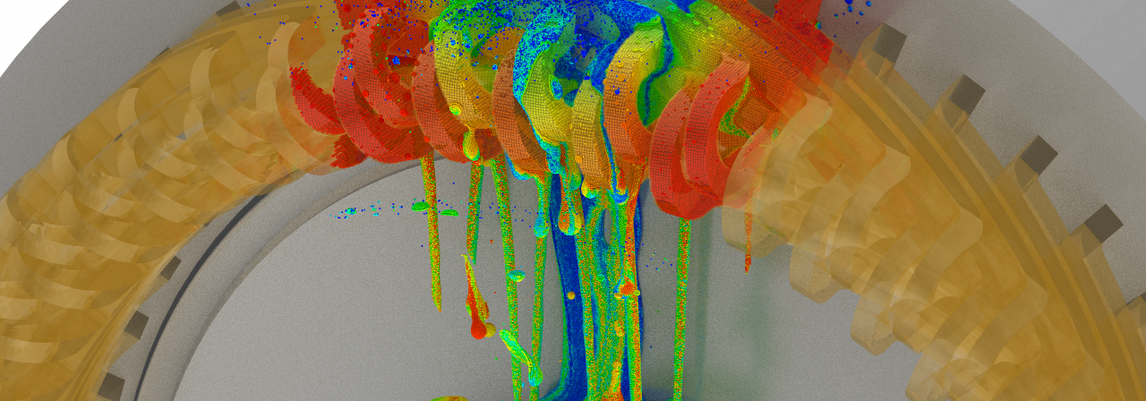
This cooling method utilizes coolant oil jets directed from the shaft onto the windings. When the oil comes into contact with the windings, it absorbs heat and cools them. The heated coolant is then collected and directed out of the motor to a heat exchanger, where it is cooled before being recirculated back into the system.
Video 3: Jet Cooling Simulation Showing the Cooling of the Copper Windings by Oil Emitted from Inlets Within the Rotating Shaft.
Another effective cooling method is jet cooling from static inlets located along the stator. The simulation focuses on optimizing the placement of these inlets to ensure efficient heat dissipation away from the stator. The goal is to maintain a uniform temperature with minimal hot spots, where cooling might be insufficient.
The inlets for the coolant are very narrow, demanding a fine particle resolution for accurate simulations. Furthermore, a very fine particle size is required at the impingement area, to resolve the thermal boundary layer adequately. With the help of CPS, the particle size can be reduced in the regions as much as necessary and increased away from these regions.
Video 4: Jet Cooling Simulation Showing the Cooling of the Copper Windings by Oil Emitted from Inlets Along the Stator.
Jacket cooling is another widely used method for managing the thermal behaviour of e-motors, providing an effective means of dissipating heat and maintaining optimal operating temperatures. This method involves surrounding the motor stator with a cooling jacket through which a coolant, typically water or a mixture of ethylene glycol and water, is circulated. As the coolant flows through the jacket, it absorbs the heat generated by the motor during operation. This heat transfer can be enhanced by using a coolant with high thermal conductivity and efficiently designing the cooling jacket, for example by including fins or channels. The heated coolant then exits the cooling jacket and is directed to a heat exchanger where it is cooled before being recirculated back into the system. This continuous loop ensures a constant removal of heat, maintaining the motor at a stable temperature even under high load conditions.
Video 5: E-motor Jacket Cooling Simulation Showing the Cooling of the Copper Windings by Water Circulating Through Cooling Channels Around the Stator.
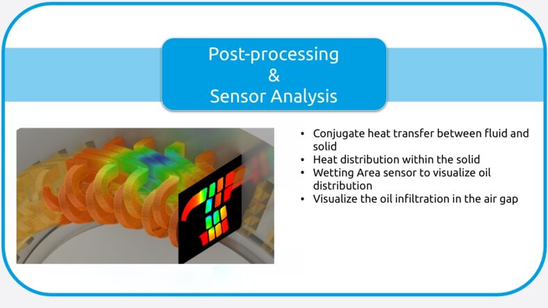
In addition to analyzing the conjugate heat transfer (CHT) between the oil and the windings, further insights can be gained into the heat distribution within the copper windings. PreonLab’s solid solver and post-processing sensor planes provide these valuable insights. Understanding the temperature distribution within the windings can help you enhance the effectiveness of the chosen cooling method. Especially by helping the user finding hotspots in the windings.
Video 6: Application of a Sensor Plane to Analyze the Heat Distribution Within the Copper Windings.
Minimizing oil infiltration in the air gap between the rotating shaft and the stator is a critical concern for e-motor design engineers. This narrow space requires precise management to ensure optimal performance and reliability. Excessive oil in the air gap can cause increased friction, reduced efficiency, and potential overheating.Therefore, minimizing oil infiltration is crucial for maintaining the motor’s integrity and performance.
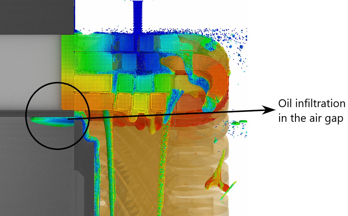
Figure 1: Oil Infiltration in the Air Gap Between the Rotating Shaft and the Stator.
Cooling is crucial for keeping electric motors (e-motors) running smoothly and efficiently. PreonLab’s simulation capability makes cooling analysis and optimization easier and more effective. By using Smoothed-Particle Hydrodynamics (SPH), PreonLab skips the usual complex steps of surface preparation and meshing, saving a lot of time and effort. Its Continuous Particle Size (CPS) feature is a game-changer, allowing for precise simulations by adjusting particle sizes to capture fine details where it’s needed most while still being efficient. Additionally, PreonLab’s GPU and multi-GPU support can further reduce simulation time. You can find out more about the significant performance boost here. With these capabilities, you can quickly get valuable insights, optimize cooling strategies, and design e-motors to perform reliably and efficiently.