Impinging Jet Benchmark for E-Motor Cooling Applications

December 08, 2022
Loïc Wendling and Siddharth Marathe

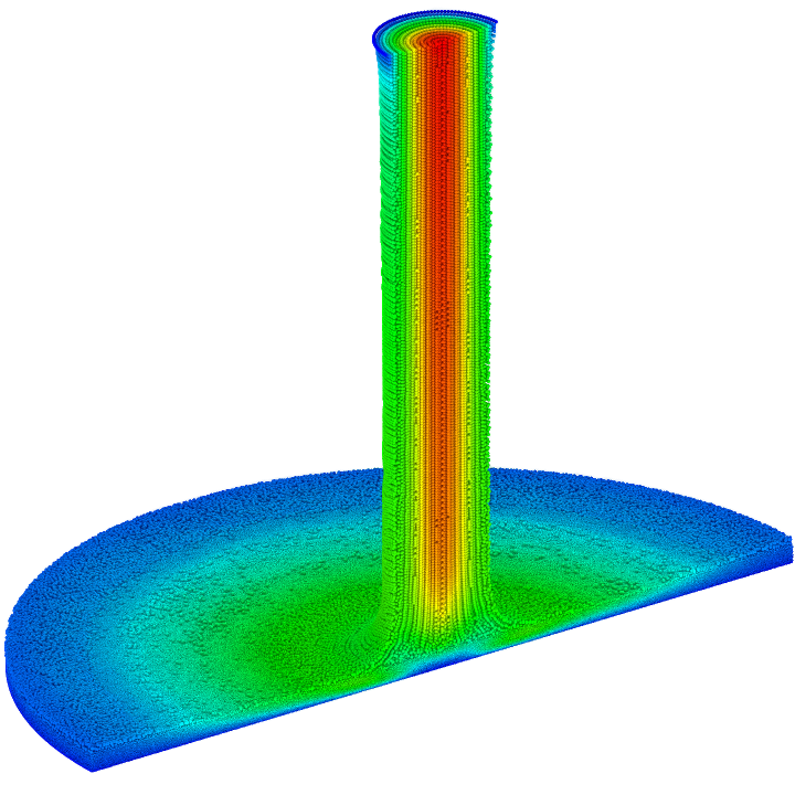
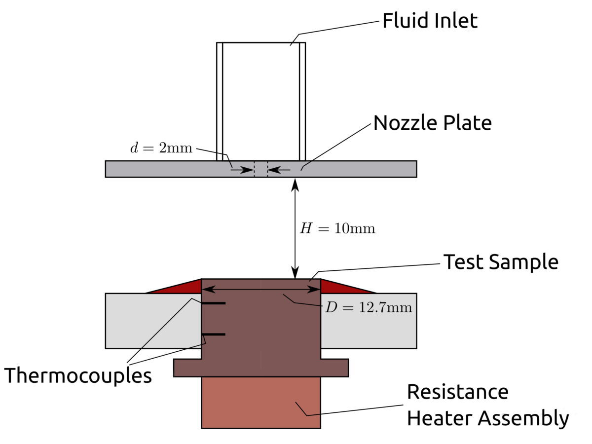
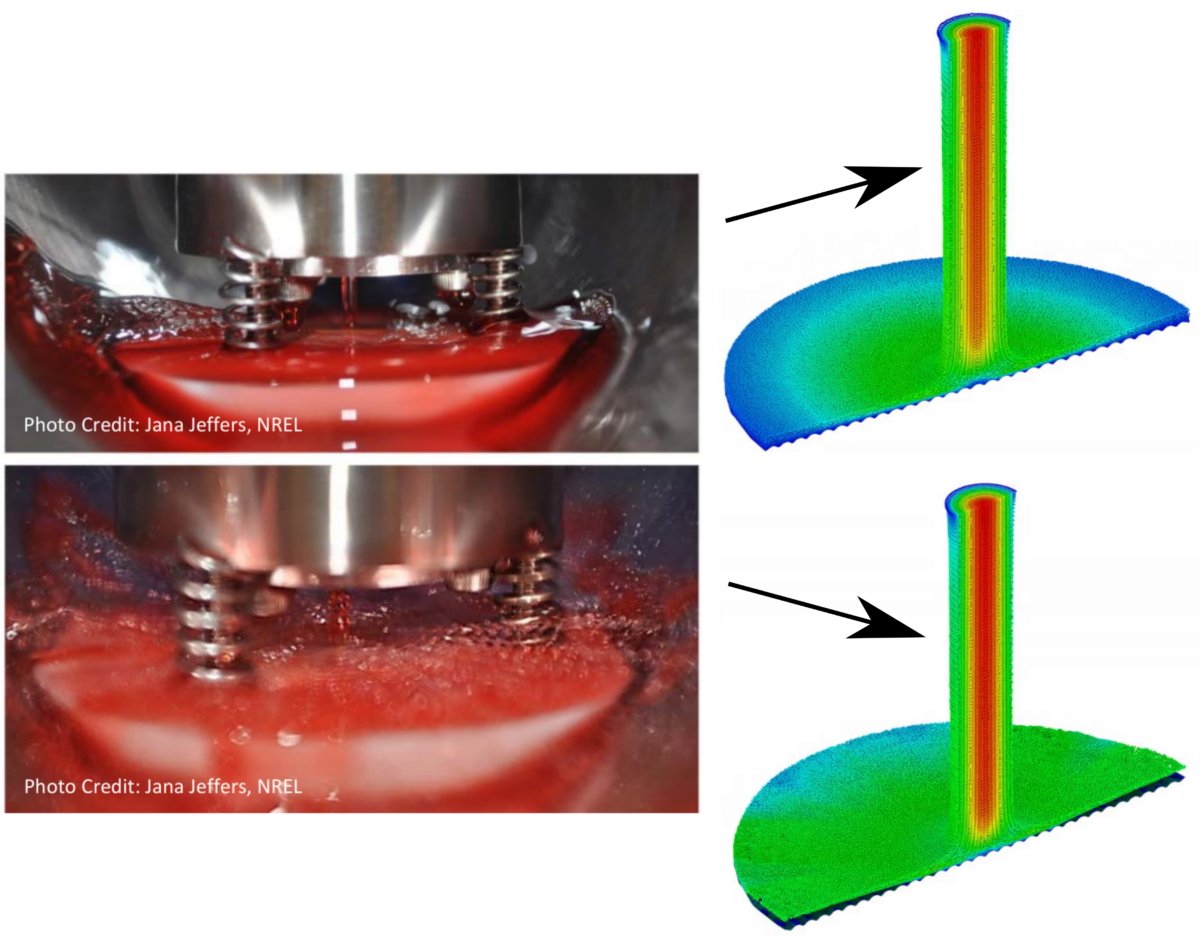
This test case aims to reproduce the results from the experiment done by Bennion and Gilberto [1] with PreonLab. They devised an experiment that measures the heat transfer of an impinging oil jet under different conditions. Some of those conditions are relevant for Electric Motor (E-Motor) cooling applications.

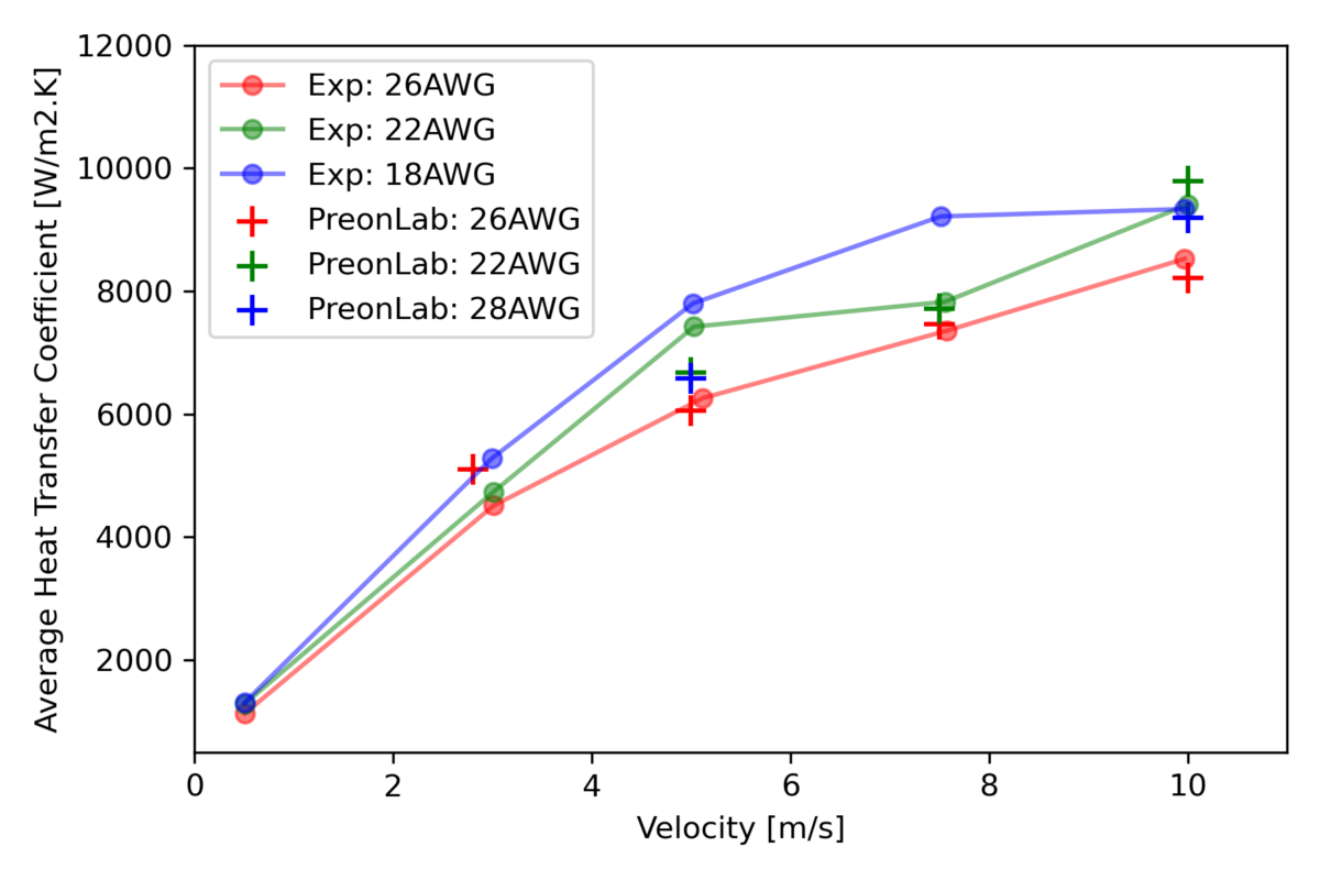
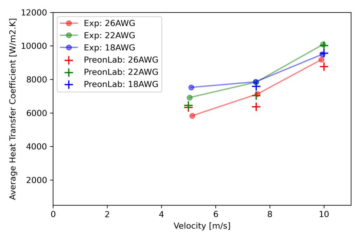
The study is divided into two parts. The goal of the first part is to validate the simulation against both experimental data and existing empirical models on a flat target. For the second part, the flat target is replaced by a textured surface replicating the surface of a copper end-winding inside an E-Motor.

Share:

What are the challenges?

Impinging jet simulations are challenging to perform because of the strong non-linearities in the temperature field that require a fine resolution to capture accurately. For this reason, the multi-level refinement feature of PreonLab is important to optimize the runtime. Smaller particles will also result in an increase in the total number of particles in the domain and thereby an increase in the computational effort. To alleviate this problem the high parallelization capabilities of PreonLab help in keeping the turnaround time low.

Another important aspect is the robust measurement of the heat transfer. The thermal sensor of PreonLab allows the computation of the distribution of heat transfer and heat transfer coefficient on the target surface in a reliable and convenient manner.

Finally, the cooling oil used has a viscosity that strongly depends on the temperature of the material. To improve the realism of the simulation, the temperature-based viscosity feature, which enables us to adjust the viscosity per particle based on its temperature, is used.

What can be learnt from the study?

This benchmark presents an opportunity to validate PreonLab against experimental data and empirical models for impinging jet cooling, an important industrial phenomenon. From this study we can also devise a workflow that will be useful for the end goal which is to simulate the cooling inside electric machines.

Setup

Experimental setup

The simulation setup is based on the experimental setup described in [1] and is shown in Figure 1. Oil is injected at the top of the system at a controlled temperature. The oil passes through a nozzle plate with a 2 mm opening meant to focus the oil into a jet. The jet impinges on a test sample made of copper. This target is placed 10 mm away from the nozzle and measures 12.7 mm in diameter.

Figure 1: Setup of the experiment.

The surface of the test sample can either be flat or textured to mimic the copper windings found in electric machines as shown in Figure 2. For the winding targets, 3 wire gauges are considered: 18, 22, and 26 American Wire Gauge (AWG) also shown in Figure 2.

Figure 2: The various targets used.

In the experiment, a resistance heater is placed underneath the copper target to mimic the copper loss of an E-Motor. The thermocouples built into the copper target are used in conjunction with the resistive heater to maintain the temperature of the top surface at 110 °C.


Simulation setup

For the simulation setup, adaptive refinement is used in the vicinity of the test sample to resolve the non-linearities near this boundary. Away from it, the particle size can remain coarse to reduce the computational effort. Like in the experiment, the temperature of the target surface is maintained at 110 °C via a temperature boundary condition (Dirichlet boundary condition). A developed pipe flow velocity distribution is used at the inlet. The transmission oil used is called Ford Mecron Oil [2]. Its properties alongside the simulation setup are provided in Table 1.

Table 1: Simulation setup

Once the simulation has converged, we can measure the local heat flux on the test sample and derive the average heat flux on the plate and the associated Heat Transfer Coefficient (HTC). For this application, the HTC is defined as:

$$ h = \frac{q}{T_\textrm{wall} – T_\textrm{jet}} $$

Where \(q\), \(T_\textrm{wall}\), \(T_\textrm{jet}\), are respectively the heat flux, the wall temperature, and the temperature of the jet at the inlet. In the newly released PreonLab version 5.3, the temperature of the jet inlet, which is our reference temperature, can now be set manually by the user, thereby, simplifying the workflow.

Results

Flat Surface Target

The resulting impinging jet obtained with PreonLab can be seen in Figure 3. After impinging on the plate, the oil jet spreads outwards until the entire target is covered. As the oil moves outward, it slows down leading to an increase in the oil film thickness. This phenomenon can also be seen in Figure 3, where the oil film thickness increases toward the edge of the disc.

Figure 3: A cross-section of the result of the impinging jet on a flat surface.

The average HTC as a function of the inlet velocity is shown in Figure 4. The results from PreonLab follow closely (within 10% of relative error) the experimental average HTC (“Exp” in the plot) for the whole range of inlet velocities, closely (within 10% of relative error). During the experiment, Bennion and Gilberto [1] also compared their results with the available empirical models for heat transfer impinging jets. The predictions from the models are also added in Figure 4 (“Ma” [4], “Leland” [3], and “Metzger” [5]). They also compare favorably with the results from PreonLab.

Figure 4: Average heat transfer coefficient as a function of velocity.

Winding Targets

Now we change the target type and use a textured surface mimicking the end-winding of an E-Motor (Figures 2.b-d). Several wire gauges have been simulated (18, 22, and 26 AWG). Figure 5 top right shows the simulated jet at a low Reynolds number (jet velocity = 5 m/s) and Figure 5 bottom right shows the same jet at a high Reynolds number (jet velocity = 10 m/s). At high Reynolds number, the oil film lifts off the plate. The same behavior has been witnessed in the experiment (see Figure 5 bottom left).

Figure 5: Comparison between photos of the experiment [1] (left) and rendered simulation results from PreonLab (right). At low Reynolds number (comparison above) the oil does not deflect off the surface. At high Reynolds number (comparison below) the oil is deflected.

Figures 6-8 shows the comparisons between the simulation result and the experimental data at 50, 70, and 90 °C respectively. PreonLab is in good agreement with the experiment for the range of velocities, inlet temperatures, and wire gauges studied in the source paper. In most cases, the heat transfer ranking between wire gauges matches well for both studies.

Figure 6: Average heat transfer coefficient of the plate for various inlet velocities and various wire gauges at 50 °C.

Figure 7: Average heat transfer coefficient of the plate for various inlet velocities and various wire gauges at 70 °C.

Figure 8: Average heat transfer coefficient of the plate for various inlet velocities and various wire gauges at 90 °C.

Conclusion

This benchmark successfully proved that PreonLab can capture the complex heat transfer phenomena generated by an impinging oil jet. When the target is flat, the heat transfer measured from the impinging jet simulated with PreonLab matches the experiment from the paper as well as the corresponding impinging jet empirical models. When realistic targets mimicking the end-winding with a variety of wire gauges are used, PreonLab maintained a close correlation with the experiment for various inlet velocities and temperatures.

References

[1] Bennion K. and Moreno G., Convective Heat Transfer Coefficients of Automatic Transmission Fluid Jets with Implications for Electric Machine Thermal Management. In International Electronic Packaging Technical Conference and Exhibition, volume 56901, page V003T04A010. American Society of Mechanical Engineers, 2015.

[2] Ford Motor Company, Product Data Sheet Mercon LV, link 

[3] Leland J.E. and Pais M.R., Free Jet Impingement Heat Transfer of a High Prandtl Number Fluid Under Conditions of Highly Varying Properties. Journal of Heat Transfer, 121(3):592–597, 08 1999.

[4] Ma C.F., Zheng Q., and Ko S.Y., Local Heat Transfer and Recovery Factor with Impinging Free-Surface Circular Jets of Transformer Oil. International Journal of Heat and Mass Transfer, 40(18):4295–4308, 1997.

[5] Metzger D.E., Cummings K.N., and Ruby W.A., Effects of Prandtl Number on Heat Transfer Characteristics of Impinging Liquid Jets. In International Heat Transfer Conference Digital Library, 1974.

RELATED ARTICLES

LEARN MORE ABOUT PreonLab Updates

How to get started with
Preonlab CFD software?
Get in Touch